ESP32-CAM Video Streaming Server Connecting I2C and SPI Displays
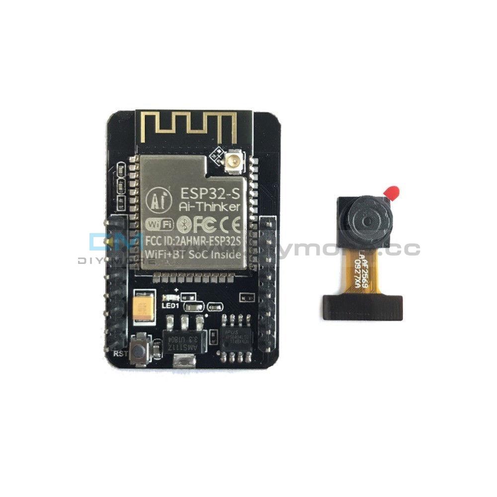
ESP-32 CAM module with camera from Diymore
An example of use is here .
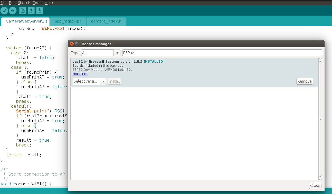
Pre-installed libraries: Esp32 board in Arduino Ide Windows / Esp32 board in Arduino Ide Linux and Mac
Detailed settings are in the article.
In my case, I used the AI-THINKER module so uncommented
#define CAMERA_MODEL_AI_THINKER
The functionality of face recognition did not work for me. The comment in the article was helpful.
It seems that face recognition is no longer working (at least with the example program) when using the 1.02 ESP core. Rolling back to the 1.01 core and using the example program belonging to that core, will 'fix' it
Having rolled back to the previous version of library 1.01 everything worked.
I have a pair of I2C 128x64 and TFT SPI 128x128 displays
Article OV7670 with FIFO how to connect the camera to the display if you do not have a CAM module. Support OV2640 and OV7670 cameras
At the time of writing, the following worked for me
ESP32 camera + Wifi Server + I2C Display (AdaFruit)
ESP32 camera + SPI Display 1.44 "TFT 128x128 v1.1 (AdaFruit)
ESP32 camera + SPI Display 1.8 "TFT 128 * 160 (Espressif library)
The WiFi driver conflicts with the SPI bus. Possible solution to use a different library. The problem arose at the time of the initialization of the WiFi module.
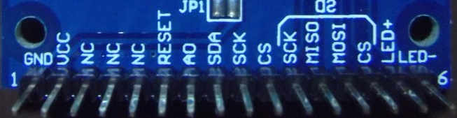
The main problem is that the ESP32-CAM module has a limited number of free legs. Part of the ports is used for the camera, part in parallel with the sd-card. The sd-card connector is installed on the board. Another conclusion (IO4) is the LED flashlight.
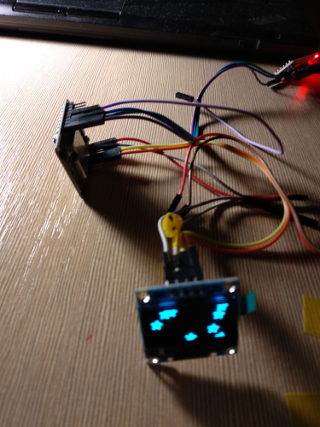
I2C Display B / W is not of particular interest for real use with the image received from the camera. TFT color and high resolution. On it you can already see the face. On such a display or a little higher resolution, you can make the Door Eye
I will say right away that the library from AdaFruit is not the fastest. I managed to display a couple of frames per second. It is more promising to use libraries that work at a low level. But I was not able to get an ESP32_TFT_library with my display 1.44 "128x128 SPI V1.1. Maybe ILI9163 is not supported. I took 1.8" 128 * 160 SPI TFT and I managed to squeeze about 12 FPS! Link
There are a couple of libraries that work faster. But some are not ported for esp-32 ( link ):
4.98 sec Adafruit_ST7735
1.71 sec ST7735X_kbv
1.30 sec PDQ_ST7735
The video looks impressive:
When usingtwo ports, one of the HSPI or VSPI hardware ports on the microcontroller and display with the ILI9341 driver can receive 30 frames per second ( link ).
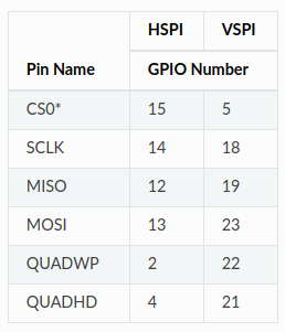
But as I said earlier in the ESP32-CAM module, only one SPI is free. It is displayed on the following PINS:
IO2 - DC (A0)
IO14 - CLK
IO15 - CS
IO13 - MOSI (SDA)
IO12 - MISO (Input. Not Used)
IO0 - BCKL (Backlight. Not used)
IO16 - RST


The first library I tried was AdaFruit SSD1306
When working in esp32, I2C emulation is used. Involved IO14 and IO15. Almost any free ports can be used, not the H / W bus is used.
How to connect Monochrome 0.96 "i2c OLED display . You need to pay attention to the display address on the I2C bus. In this case, 0x3C


Wiring diagram:
IO2 - A0
IO14 - SCK
IO15 - CS
IO13 - SDA
IO16 - RESET
The board also has an SD-card reader
IO configuration:
Install the environment and development environment from Espressif . Detailed instructions on how to do this .
Install the library . Two corrections need to be made to assemble the library.
Makefile:
components / tft / tftspi.c:
→ Patch
Then install the ESP32 Camera Driver .
Configure:
#. $ HOME / esp / esp-idf / export.sh
# idf.py menuconfig


Allow access for the USB port for firmware and monitoring:
#sudo chmod 777 / dev / ttyUSB0
We collect and fill:
#make -j4 && make flash
12FPS is achieved through packet writing using the send_data method. Recording is not pixel by pixel, but a whole line equal to the width of the screen:
→ Gist
FRAME_WIDTH is the frame width of 320 pixels for QVGA
In fact, we see a 128 * 160 window from the full frame on the display
Log for configuration with a single camera buffer (config.fb_count = 1)
Capture camera time: 32 ms
Send buffer time: 47 ms
Capture frame ok.
Result
1000 / (32 + 47) = 12.65 FPS
By using the second buffer of the camcorder, the buffer in some cycles is obtained instantly. At first, the complete cycle is obtained using less than one buffer, but then this time “runs on”. The interval between cycles is floating.
Several times I caught in the logs "Brownout detector was triggered" so I turned off the detector. Because at first I fed the backlight display from the 3.3V output of the ESP32-CAM
ESP32 low-cost functional module. There is a catastrophic lack of conclusions for implemented ports in the CAM version of the board, so choose the CAM version if you really need a camera.
ESP32-CAM Video Streaming Server
An example of use is here .
Pre-installed libraries: Esp32 board in Arduino Ide Windows / Esp32 board in Arduino Ide Linux and Mac
Detailed settings are in the article.
In my case, I used the AI-THINKER module so uncommented
#define CAMERA_MODEL_AI_THINKER
The functionality of face recognition did not work for me. The comment in the article was helpful.
It seems that face recognition is no longer working (at least with the example program) when using the 1.02 ESP core. Rolling back to the 1.01 core and using the example program belonging to that core, will 'fix' it
Having rolled back to the previous version of library 1.01 everything worked.
I have a pair of I2C 128x64 and TFT SPI 128x128 displays
Article OV7670 with FIFO how to connect the camera to the display if you do not have a CAM module. Support OV2640 and OV7670 cameras
At the time of writing, the following worked for me
ESP32 camera + Wifi Server + I2C Display (AdaFruit)
ESP32 camera + SPI Display 1.44 "TFT 128x128 v1.1 (AdaFruit)
ESP32 camera + SPI Display 1.8 "TFT 128 * 160 (Espressif library)
The WiFi driver conflicts with the SPI bus. Possible solution to use a different library. The problem arose at the time of the initialization of the WiFi module.
The main problem is that the ESP32-CAM module has a limited number of free legs. Part of the ports is used for the camera, part in parallel with the sd-card. The sd-card connector is installed on the board. Another conclusion (IO4) is the LED flashlight.
I2C Display B / W is not of particular interest for real use with the image received from the camera. TFT color and high resolution. On it you can already see the face. On such a display or a little higher resolution, you can make the Door Eye
I will say right away that the library from AdaFruit is not the fastest. I managed to display a couple of frames per second. It is more promising to use libraries that work at a low level. But I was not able to get an ESP32_TFT_library with my display 1.44 "128x128 SPI V1.1. Maybe ILI9163 is not supported. I took 1.8" 128 * 160 SPI TFT and I managed to squeeze about 12 FPS! Link
There are a couple of libraries that work faster. But some are not ported for esp-32 ( link ):
4.98 sec Adafruit_ST7735
1.71 sec ST7735X_kbv
1.30 sec PDQ_ST7735
The video looks impressive:
When using
But as I said earlier in the ESP32-CAM module, only one SPI is free. It is displayed on the following PINS:
IO2 - DC (A0)
IO14 - CLK
IO15 - CS
IO13 - MOSI (SDA)
IO12 - MISO (Input. Not Used)
IO0 - BCKL (Backlight. Not used)
IO16 - RST
The first library I tried was AdaFruit SSD1306
I2C 128x64 Blue OLED Display
#include <Wire.h> #include <Adafruit_GFX.h> #include <Adafruit_SSD1306.h> #define SCREEN_WIDTH 128 // OLED display width, in pixels #define SCREEN_HEIGHT 64 // OLED display height, in pixels // Declaration for an SSD1306 display connected to I2C (SDA, SCL pins) #define OLED_RESET -1 // Reset pin # (or -1 if sharing Arduino reset pin) Adafruit_SSD1306 display; void init_display(){ pinMode(14,INPUT_PULLUP); pinMode(15,INPUT_PULLUP); Wire.begin(14,15); display = Adafruit_SSD1306(SCREEN_WIDTH, SCREEN_HEIGHT, &Wire, OLED_RESET); if(!display.begin(SSD1306_SWITCHCAPVCC, 0x3C)) { // Address 0x3D for 128x64 Serial.println(F("SSD1306 allocation failed")); for(;;); // Don't proceed, loop forever } .... camera_capture ()
#define BACKCOLOR 0x0000 // Black #define PIXELCOLOR 0xFFFF // White #define FRAME_WIDTH 320 #define FRAME_HEIGHT 240 uint16_t pixel_color = 0; esp_err_t camera_capture(){ //acquire a frame camera_fb_t * fb = esp_camera_fb_get(); if (!fb) { ESP_LOGE(TAG, "Camera Capture Failed"); return ESP_FAIL; } int i = 0; for(int y = 0; y < SCREEN_HEIGHT; y++){ for(int x = 0; x < SCREEN_WIDTH; x++){ i = y * FRAME_WIDTH + x; // FRAMESIZE_QVGA // 320x240 char ch = (char)fb->buf[i]; if (ch > 128) pixel_color = WHITE; else pixel_color = BLACK; // Draw a single pixel in white display.drawPixel(x, y, pixel_color); } } display.display(); //return the frame buffer back to the driver for reuse esp_camera_fb_return(fb); Serial.println("Capture frame ok."); return ESP_OK; } When working in esp32, I2C emulation is used. Involved IO14 and IO15. Almost any free ports can be used, not the H / W bus is used.
How to connect Monochrome 0.96 "i2c OLED display . You need to pay attention to the display address on the I2C bus. In this case, 0x3C
SPI Display 1.8 "TFT 128 * 160 Espressif Library
Wiring diagram:
IO2 - A0
IO14 - SCK
IO15 - CS
IO13 - SDA
IO16 - RESET
The board also has an SD-card reader
IO configuration:
// Configuration for other boards, set the correct values for the display used //---------------------------------------------------------------------------- #define DISP_COLOR_BITS_24 0x66 //#define DISP_COLOR_BITS_16 0x55 // Do not use! // ############################################# // ### Set to 1 for some displays, ### // for example the one on ESP-WROWER-KIT ### // ############################################# #define TFT_INVERT_ROTATION 0 #define TFT_INVERT_ROTATION1 0 // ################################################ // ### SET TO 0X00 FOR DISPLAYS WITH RGB MATRIX ### // ### SET TO 0X08 FOR DISPLAYS WITH BGR MATRIX ### // ### For ESP-WROWER-KIT set to 0x00 ### // ################################################ #define TFT_RGB_BGR 0x08 // ############################################################## // ### Define ESP32 SPI pins to which the display is attached ### // ############################################################## // The pins configured here are the native spi pins for HSPI interface // Any other valid pin combination can be used #define PIN_NUM_MISO 12 // SPI MISO #define PIN_NUM_MOSI 13 // SPI MOSI #define PIN_NUM_CLK 14 // SPI CLOCK pin #define PIN_NUM_CS 15 // Display CS pin #define PIN_NUM_DC 2 // Display command/data pin #define PIN_NUM_TCS 0 // Touch screen CS pin (NOT used if USE_TOUCH=0) // -------------------------------------------------------------- // ** Set Reset and Backlight pins to 0 if not used ! // ** If you want to use them, set them to some valid GPIO number #define PIN_NUM_RST 0 // GPIO used for RESET control #define PIN_NUM_BCKL 0 // GPIO used for backlight control #define PIN_BCKL_ON 0 // GPIO value for backlight ON #define PIN_BCKL_OFF 1 // GPIO value for backlight OFF // -------------------------------------------------------------- // ####################################################### // Set this to 1 if you want to use touch screen functions // ####################################################### #define USE_TOUCH TOUCH_TYPE_NONE // ####################################################### // ####################################################################### // Default display width (smaller dimension) and height (larger dimension) // ####################################################################### #define DEFAULT_TFT_DISPLAY_WIDTH 128 #define DEFAULT_TFT_DISPLAY_HEIGHT 160 // ####################################################################### #define DEFAULT_GAMMA_CURVE 0 #define DEFAULT_SPI_CLOCK 32000000 #define DEFAULT_DISP_TYPE DISP_TYPE_ST7735B //---------------------------------------------------------------------------- #define TFT_INVERT_ROTATION 0 #define TFT_INVERT_ROTATION1 1 #define TFT_INVERT_ROTATION2 0 Install the environment and development environment from Espressif . Detailed instructions on how to do this .
Install the library . Two corrections need to be made to assemble the library.
Makefile:
+ CFLAGS += -Wno-error=tautological-compare \ + -Wno-implicit-fallthrough \ + -Wno-implicit-function-declaration components / tft / tftspi.c:
+ #include "driver/gpio.h → Patch
Then install the ESP32 Camera Driver .
Configure:
#. $ HOME / esp / esp-idf / export.sh
# idf.py menuconfig
Allow access for the USB port for firmware and monitoring:
#sudo chmod 777 / dev / ttyUSB0
We collect and fill:
#make -j4 && make flash
12FPS is achieved through packet writing using the send_data method. Recording is not pixel by pixel, but a whole line equal to the width of the screen:
esp_err_t camera_capture(){ uint32_t tstart, t1, t2; tstart = clock(); //acquire a frame camera_fb_t * fb = esp_camera_fb_get(); if (!fb) { printf("Camera Capture Failed\n"); return ESP_FAIL; } t1 = clock() - tstart; printf("Capture camera time: %u ms\r\n", t1); int i = 0, bufPos = 0; uint8_t hb, lb; color_t color; color_t *color_line = heap_caps_malloc(_width*3, MALLOC_CAP_DMA); tstart = clock(); for(int y = 0; y < _height; y++) { bufPos = 0; for(int x = 0; x < _width; x++) { i = (y * FRAME_WIDTH + x) << 1; hb = fb->buf[i] ; lb = fb->buf[i + 1]; color.r = (lb & 0x1F) << 3; color.g = (hb & 0x07) << 5 | (lb & 0xE0) >> 3; color.b = hb & 0xF8; color_line[bufPos] = color; bufPos++; // TFT_drawPixel(0, 0, color, 1); } disp_select(); send_data(0, y, _width-1, y, _width, color_line); wait_trans_finish(1); disp_deselect(); } free(color_line); t1 = clock() - tstart; printf("Send buffer time: %u ms\r\n", t1); esp_camera_fb_return(fb); printf("Capture frame ok.\n"); return ESP_OK; } Camera configuration
// #if defined(CAMERA_MODEL_AI_THINKER) #define PWDN_GPIO_NUM 32 #define RESET_GPIO_NUM -1 #define XCLK_GPIO_NUM 0 #define SIOD_GPIO_NUM 26 #define SIOC_GPIO_NUM 27 #define Y9_GPIO_NUM 35 #define Y8_GPIO_NUM 34 #define Y7_GPIO_NUM 39 #define Y6_GPIO_NUM 36 #define Y5_GPIO_NUM 21 #define Y4_GPIO_NUM 19 #define Y3_GPIO_NUM 18 #define Y2_GPIO_NUM 5 #define VSYNC_GPIO_NUM 25 #define HREF_GPIO_NUM 23 #define PCLK_GPIO_NUM 22 void camera_init_(){ camera_config_t config; config.ledc_channel = LEDC_CHANNEL_0; config.ledc_timer = LEDC_TIMER_0; config.pin_d0 = Y2_GPIO_NUM; config.pin_d1 = Y3_GPIO_NUM; config.pin_d2 = Y4_GPIO_NUM; config.pin_d3 = Y5_GPIO_NUM; config.pin_d4 = Y6_GPIO_NUM; config.pin_d5 = Y7_GPIO_NUM; config.pin_d6 = Y8_GPIO_NUM; config.pin_d7 = Y9_GPIO_NUM; config.pin_xclk = XCLK_GPIO_NUM; config.pin_pclk = PCLK_GPIO_NUM; config.pin_vsync = VSYNC_GPIO_NUM; config.pin_href = HREF_GPIO_NUM; config.pin_sscb_sda = SIOD_GPIO_NUM; config.pin_sscb_scl = SIOC_GPIO_NUM; config.pin_pwdn = PWDN_GPIO_NUM; config.pin_reset = RESET_GPIO_NUM; config.xclk_freq_hz = 20000000; config.fb_count = 2; // for display config.frame_size = FRAMESIZE_QVGA; config.pixel_format = PIXFORMAT_RGB565; // camera init esp_err_t err = esp_camera_init(&config); if (err != ESP_OK) { printf("Camera init failed with error 0x%x", err); return; } printf("Camera init OK\n"); } → Gist
FRAME_WIDTH is the frame width of 320 pixels for QVGA
config.frame_size = FRAMESIZE_QVGA; // 320x240 In fact, we see a 128 * 160 window from the full frame on the display
Log for configuration with a single camera buffer (config.fb_count = 1)
Capture camera time: 32 ms
Send buffer time: 47 ms
Capture frame ok.
Result
1000 / (32 + 47) = 12.65 FPS
Log for configuration with two camcorder buffers (config.fb_count = 2)
Capture camera time: 39 ms
Send buffer time: 63 ms
Capture frame ok.
Capture camera time: 0 ms
Send buffer time: 59 ms
Capture frame ok.
Capture camera time: 0 ms
Send buffer time: 34 ms
Capture frame ok.
Capture camera time: 40 ms
Send buffer time: 64 ms
Capture frame ok.
Capture camera time: 0 ms
Send buffer time: 59 ms
Capture frame ok.
Capture camera time: 0 ms
Send buffer time: 34 ms
Capture frame ok.
Capture camera time: 40 ms
Send buffer time: 63 ms
Capture frame ok.
Capture camera time: 0 ms
Send buffer time: 60 ms
Capture frame ok.
Capture camera time: 0 ms
Send buffer time: 34 ms
Capture frame ok.
Capture camera time: 39 ms
Send buffer time: 63 ms
Capture frame ok.
Capture camera time: 0 ms
Send buffer time: 60 ms
Capture frame ok.
Capture camera time: 1 ms
Send buffer time: 34 ms
Capture frame ok.
Capture camera time: 40 ms
Send buffer time: 63 ms
Capture frame ok.
Capture camera time: 0 ms
Send buffer time: 60 ms
Capture frame ok.
Capture camera time: 0 ms
Send buffer time: 34 ms
Capture frame ok.
Capture camera time: 40 ms
Send buffer time: 63 ms
Capture frame ok.
Capture camera time: 0 ms
Send buffer time: 59 ms
Capture frame ok.
Capture camera time: 0 ms
Send buffer time: 35 ms
Capture frame ok.
Send buffer time: 63 ms
Capture frame ok.
Capture camera time: 0 ms
Send buffer time: 59 ms
Capture frame ok.
Capture camera time: 0 ms
Send buffer time: 34 ms
Capture frame ok.
Capture camera time: 40 ms
Send buffer time: 64 ms
Capture frame ok.
Capture camera time: 0 ms
Send buffer time: 59 ms
Capture frame ok.
Capture camera time: 0 ms
Send buffer time: 34 ms
Capture frame ok.
Capture camera time: 40 ms
Send buffer time: 63 ms
Capture frame ok.
Capture camera time: 0 ms
Send buffer time: 60 ms
Capture frame ok.
Capture camera time: 0 ms
Send buffer time: 34 ms
Capture frame ok.
Capture camera time: 39 ms
Send buffer time: 63 ms
Capture frame ok.
Capture camera time: 0 ms
Send buffer time: 60 ms
Capture frame ok.
Capture camera time: 1 ms
Send buffer time: 34 ms
Capture frame ok.
Capture camera time: 40 ms
Send buffer time: 63 ms
Capture frame ok.
Capture camera time: 0 ms
Send buffer time: 60 ms
Capture frame ok.
Capture camera time: 0 ms
Send buffer time: 34 ms
Capture frame ok.
Capture camera time: 40 ms
Send buffer time: 63 ms
Capture frame ok.
Capture camera time: 0 ms
Send buffer time: 59 ms
Capture frame ok.
Capture camera time: 0 ms
Send buffer time: 35 ms
Capture frame ok.
By using the second buffer of the camcorder, the buffer in some cycles is obtained instantly. At first, the complete cycle is obtained using less than one buffer, but then this time “runs on”. The interval between cycles is floating.
Several times I caught in the logs "Brownout detector was triggered" so I turned off the detector. Because at first I fed the backlight display from the 3.3V output of the ESP32-CAM
#include "soc/rtc_cntl_reg.h" ... WRITE_PERI_REG(RTC_CNTL_BROWN_OUT_REG, 0); //disable brownout detector Conclusion
ESP32 low-cost functional module. There is a catastrophic lack of conclusions for implemented ports in the CAM version of the board, so choose the CAM version if you really need a camera.
More posts:
All Posts